Metal Injection Moulding (MIM) Flow
Complex geometry at scale with precision tolerance control. Net-shape production for demanding applications.
Get Quote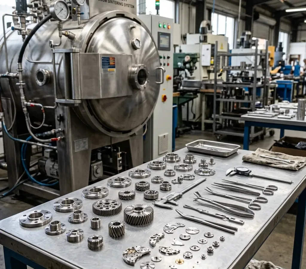
The MIM Process
Four critical stages transform metal powder into precision components.
Design Freedom
Create complex geometries that would be impossible or cost-prohibitive with traditional manufacturing methods. MIM excels at intricate features, undercuts, and thin walls.
Cost at Scale
Net-shape production minimizes material waste and secondary operations. Ideal for medium to high volume production runs where tooling costs are amortized.
Material Versatility
Process a wide range of metals and alloys including stainless steel, titanium, tool steels, and specialty alloys with excellent material properties.
MIM Process Overview
From powder to precision part: understanding the complete metal injection moulding workflow.
Feedstock Preparation
Fine metal powders are precisely blended with polymer and wax binders to create a homogeneous feedstock that can flow like plastic during injection moulding. The powder-to-binder ratio is carefully controlled to ensure optimal flow characteristics and final part density.
Injection Moulding
The feedstock is heated and injected into precision tooling under high pressure to create the green part. This stage captures complex geometry and fine details while multiple cavities support high-volume efficiency.
Debinding
Binder removal converts the green part into a porous brown part. Careful control of temperature, atmosphere, and time helps prevent cracking, blistering, or warping.
Sintering
High-temperature sintering, typically 1200-1400 C, densifies the metal particles through atomic diffusion. Shrinkage is engineered into the tooling design.
Secondary Operations
As needed, parts undergo precision machining, heat treatment, or surface finishing such as plating, coating, or polishing. Fu Yu's integrated capabilities support smooth transition between MIM and secondary processes.
Inspection & Validation
Dimensional metrology verifies tolerances and geometry. Material verification through density measurement, hardness testing, and metallurgical analysis supports specification compliance.
Visual Process Flow
From feedstock to final part: the transformation journey.

Feedstock Pellets
Metal powder + binder
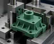
Green Part
After injection moulding
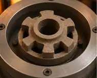
Brown Part
After debinding, porous
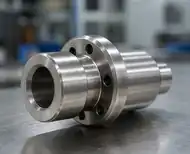
Sintered Part
Final dense metal part
When to Choose MIM
Comparing MIM to CNC machining and casting for informed manufacturing decisions.
| Criteria | MIM | CNC Machining | Casting |
|---|---|---|---|
| Complexity | Excellent Complex geometries, undercuts, thin walls | Limited Constrained by tool access | Good Complex shapes possible |
| Volume | 10K-1M+ Best at medium-high volume | 1-10K Low to medium volume | High Very high volumes economical |
| Tolerances | +/-0.3-0.5% Good tolerance control | Excellent Tightest tolerances | Moderate Often requires machining |
| Material Waste | Minimal Net-shape production | High Subtractive process | Low Near net-shape |
| Tooling Cost | Medium-High Upfront investment | Low Standard tooling | High Expensive molds |
Frequently Asked Questions
Common questions about the MIM process and capabilities.
What are green parts and brown parts in metal injection moulding?
Green parts are the initial molded components containing metal powder and binder. Brown parts are the intermediate stage after debinding, where binder is removed leaving a porous metal structure ready for sintering.
How does debinding work and why is it critical?
Debinding removes the polymer binder through controlled heating or chemical processes. It is critical because improper debinding can cause cracks, distortion, or incomplete binder removal that affects final part quality.
How do you control sintering shrinkage?
Shrinkage is controlled through precise feedstock formulation, tooling design that compensates for expected shrinkage, and optimized sintering parameters including temperature profiles and atmosphere control.